Arduino OpenTherm Controller
Posted on Tuesday, January 31, 2017 at 12:00 AM, 84053 views
From my point of view, home central heating system is one of the first thing, that should be managed by home automation system. Which allows you to create comfortable climate in your home regardless the outdoor weather, decrease usage of gas or electricity, save your money, and control your home heating whether you're out or on the sofa via laptop, smartphone or tablet.
The main part of each heating system is boiler. Most of the boilers can be controlled by simple on/off thermostat. However, newer boilers support power modulation and allow thermostats to adjust their heating water temperature. The boiler will use more or less gas(electricity), as appropriate, to reach the water temperature set by the thermostat. Using a simple on/off control device would greatly reduce the efficiency of the system compared to a modulating thermostat.
OpenTherm (OT) is a standard communications protocol used in central heating systems for the communication between a central heating boiler and a thermostatic controller. Official web site www.opentherm.eu. Using OpenTherm protocol you can control both your boiler’s domestic hot water temperature, as well as the temperature of the water used to heat your home. There are quite a lot manufacturers which make OpenTherm compatible boilers. Protocol specification version 2.2 you can find here. The boiler and the thermostat should be connected using two wires regardless of polarity. Voltage levels: Low level 7V, High level - 15..18V.
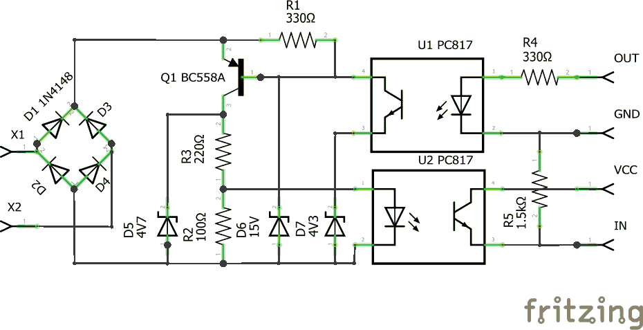
So to control boiler via arduino we should make OpenTherm to TTL levels adapter. I found schematic of DIY Opentherm Gateway, based on PIC controller, which allows to send OpenTherm commands to boiler via serial port. I was curious to understand OpenTherm protocol and features which it provides, so I decided to implement only adapter part of that schematic, and control boiler directly by arduino.
Schematic:
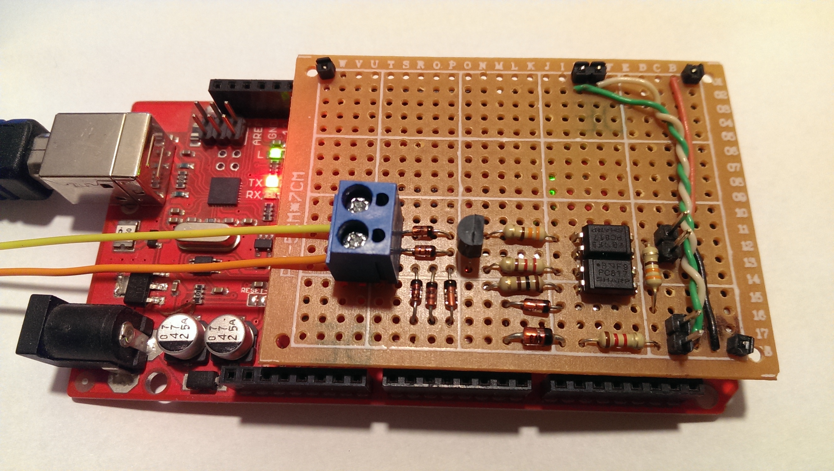
Circuit board:
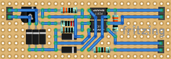
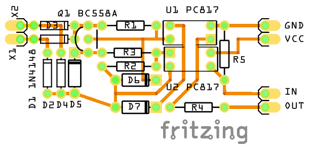
PCB:
Implementation:

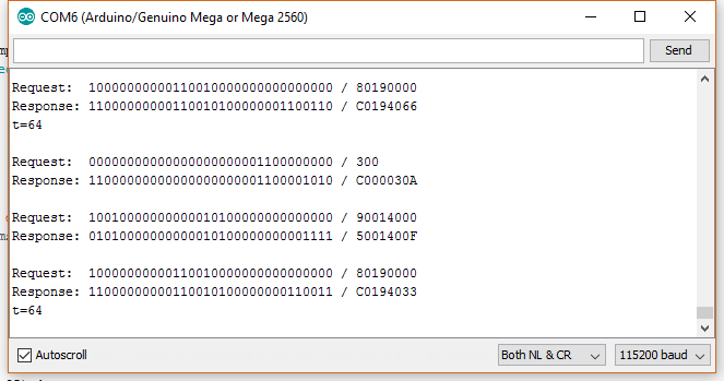
Serial port output:
Hardware:
- Opto-coupler PC817 x 2 0.2$
- PNP Transistor 0.1$
- Diode 1N4148 x 4 0.1$
- Zener Diode 4V7 0.1$
- Zener Diode 15V 0.1$
- Zener Diode 4V3 0.1$
- 1/4 Watt 5% Resistor 100 Ohm 0.01$
- 1/4 Watt 5% Resistor 220 Ohm 0.01$
- 1/4 Watt 5% Resistor 330 Ohm x 2 0.01$
- 1/4 Watt 5% Resistor 1k5 Ohm 0.01$
- Arduino Mega 2560 R3 or any Arduino Compatible 2-7$
Software:
Connections:
To connect adapter we can use any Arduino compatible controller, just choose random two GPIO pins and update two constants (OT_IN_PIN and OT_OUT_PIN) in sketch. I've made PCB like Arduino Mega compatible shield, connected to 18, 19 pins for data and 5V, GND as power supply. Boiler should be connected to adapter(instead of thermostat) via two wires using screw terminal.
Simple sketch allows to send OpenTherm requests to boiler and receive responses. There is an array (requests) of base commands:
- 0 - get status
- 1 - set central heating temperature (64oC in my case)
- 25 - get boiler water temperature
   P MGS-TYPE SPARE DATA-ID  DATA-VALUE
   0 000      0000  00000000 00000000 00000000
Where P is parity bit, you should set it to 1 if there are odd number of 1 bits in request.
MGS-TYPE - 000 for read request and 001 for write.
DATA-ID - command ID.
DATA-VALUE - 16 bit value, specific for each command.
Boiler Buderus Logamax u072-24k:
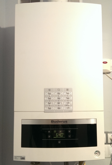
Central heating temperature is set to 64oC.
Assembled OpenTherm Adapter:
More information about assembled OpenTherm Adapter you can find here.
To Buy it, please navigate to the Shop page.


